 The Pacific War Online Encyclopedia
|
| Table of Contents |
For a discussion of armored fighting vehicles, see the article on Tanks.

During the Pacific War, most warships larger than destroyers had some degree of armor protection against bombs and gunfire, and most destroyers had some degree of splinter protection. The purpose of armor was to prevent enemy fire from penetrating to the magazines, machinery spaces, or other vital spaces of the warship so that the warship could survive a number of hits and continue fighting. Splinter protection sought to contain the damage from penetrating hits rather than to prevent such hits.
Armor defeated projectiles in one of three ways. An incoming shell might not have sufficient energy to penetrate the armor, in which case there was little damage. A shell with high energy might shatter against the armor or be so damaged that it would not detonate even if it penetrated. In the former case, the damage was slight, while in the latter case it was still much reduced. Finally, a shell coming in at a shallow angle might be deflected by the armor and do little damage.
Prior to the First World War, naval architects tried to provide some degree of armor protection to most parts of a warship. However, starting with the battleships of the Nevada class, this total protection philosophy gave way to an "all or nothing" philosophy in which those portions of a warship that could not be given heavy armor protection were given no protection at all. This was largely a response to improvements in long-range gunnery, which suggested that battle would likely take place out of the range of secondary guns. The portion of the ship protected by heavy armor typically extended from the forward turret to the aft turret and included the magazine and machinery spaces. This portion of the ship was known as the citadel. Most of the bow and stern of the ship and the upper decks were given nothing more than splinter protection.
The main element of the armor protecting the citadel was a belt of armor on each side of the ship covering the area close to the waterline. This belt protected the magazines and machinery spaces, which were usually located at or below the waterline. Small belts were fashioned from single plates, while larger belts could be fashioned from multiple plates locked together to avoid weakness at seams. Though substantial over its entire length and width, the belt was not necessarily uniform. It tended to be somewhat thicker where it was protecting magazine spaces, the most vulnerable part of a warship, and to taper off in thickness below the waterline. There was considerable variation in how much protection was provided below the waterline, ranging from minimal protection to the very deep belt on the King George V-class battleships.
At long range, shells would come in at a steeper angle (plunging fire) and could penetrate the vital spaces from above the upper edge of the belt. Thus, the belt on larger warships was supplemented with horizontal protection in the form of an armored deck. Because even plunging fire came in at a relatively shallow angle, the armored deck was usually much thinner than the belt. This also saved considerable weight, since the area of the armored deck was large. As a rule of thumb, the maximum thickness of the armored deck was about a third to a half of the maximum thickness of the belt.
In most warships, the armored deck was flat and joined the belt at its upper edge, but a few designs sloped the outer part of the armored deck so that it joined the belt at its lower edge. Sloped armored decks added an extra layer of protection behind the belt, but were less effective against plunging fire and enclosed a smaller volume than flat decks. Ships with flat armor decks often put a splinter bulkhead behind the armor belt to stop spall and shell fragments from partially penetrating hits. This bulkhead was often an upwards extension of the torpedo holding bulkhead.
Of necessity, the armored deck had openings for the boiler
uptakes and hatches for access, but these constituted a small
percentage of the area and only a lucky hit would penetrate
through one of these openings. The uptakes often had very heavy
armored grates where they passed through the armor deck; these
were often much thicker than the rest of the deck, compensating
for the inherent weakness produced by the holes through which the
exhaust passed.
The ends of the belts were closed by armored bulkheads. These were typically equal in thickness to the belts, extended to the level of the armored deck, and were joined to it. Thus, the vital spaces were protected by an armored box that offered protection from shells coming in from almost any direction and range.
As anticipated engagement ranges became greater, it became
increasingly difficult to provide adequate deck armor against
plunging fire, and aircraft bombs were also a growing
concern. The most modern battleship designs had three or more
armor decks, each fulfilling a different function. The main
armored deck retained the bulk of the horizontal armor, but a bomb
deck was placed above the armored deck that was just heavy enough
to activate fuses on armor-piercing shells and bombs so that they
would detonate before reaching the armor deck. The bomb deck also
provided considerable protection from GP bombs, and for this
reason was typically placed as high in the ship as possible. A
splinter deck was placed under the armor deck, often joining the
main belt at its lower edge, which was just heavy enough to stop
spall and shell fragments from hits that partially penetrated the
armor deck.
Naval architects also began experimenting with armor belt designs
in which the armor was sloped away from the vertical. This
increased the effectiveness of the armor by presenting a greater
thickness along the likely trajectory of incoming shells. Though
an inclined belt was more difficult to arrange than a vertical
belt, the Japanese and Americans made the effort
on all their most modern battleships. The British chose instead to
give their modern battleships a very deep vertical belt that
offered greater underwater protection. The hull outside the
internal belts of American battleships was made thick enough to
strip the caps off of armor-piercing shells, significantly
reducing their penetrating power against the main belt.
The British deep vertical belts were prompted by another
consequence of longer range engagements, which was underwater
shell hits. At close range, a shell hitting the water short of its
target was likely to ricochet off the water's surface, hitting the
side belt or (at worst) the unarmored superstructure of the ship.
At very long range, shells hitting just short of the target could
penetrate a considerable distance underwater, possibly hitting the
hull of the target below its armor belt. Conventional underwater
protection was not designed against such hits. The Americans
responded to the threat with internal armor patches protecting the
magazines.
Some warships had lightly armored boiler uptakes or armored boxes
around the magazines and steering spaces. The armor on the boiler
uptakes could not prevent penetration by a direct hit, but it
prevented penetration by splinters that would let hot exhaust
gases into the interior of the ship. The armored boxes around
magazines and steering were often quite substantial and gave
concentrated protection to these particularly vulnerable spaces.
Because shells fired at close range had more penetrating power
against belt armor, while shells fired at very long range had an
increased chance of penetrating the thinner deck armor, the
protection of an armored warship was often characterized by the zone
of immunity. This was an annular zone around the ship that
represented the likely battle ranges anticipated by the warship
designer. The inner radius of this annular zone was the closest
range at which the belt armor could resist penetration by gunfire
of the caliber against which the protection was designed. The
outer radius of the zone of immunity was the farthest range at
which the deck armor could resist penetration by plunging
fire. For example, the Iowa class had a zone of
immunity against 16"/45 shells of 18,000 to 30,000 yards (16,000
to 27,000 m).
In addition to the armored citadel, large warships had armor
protection for the turrets containing the main guns. This
protection was usually comparable to the belt protection on the
front face of the turret and somewhat thinner on the sides. The
rear armor was occasionally quite heavy, not so much for
protection as to balance the turret. The roof of the turret was
armored to provide horizontal protection analogous to the armored
deck. The barbette (the cylindrical structure on which the turret
sat, which usually extended down to the magazine) was generally
also armored, with the armor typically thicker to the sides than
fore and aft.
The gun ports on turret faces were a source of weakness, so that
a greater thickness of armor was required to give the same
protection. The turret face was usually sloped well back to
increase the likelihood of a shell ricocheting upwards off the
face.
Larger warships typically had a heavily armored conning tower
from which the command
crew could direct the activities of the ship. This armored conning
tower became controversial because it severely restricted
visibility, an important consideration in a sea fight.
Observations could only be made through narrow slits. Some degree
of armor protection (rarely more than heavy splinter protection)
was also provided for range finders and other vital fire control
elements. The U.S. Navy was unique in attempting to place all the
vital elements of the fire control system under armor, with
rangefinders build into the turrets and the main plotting room
within the armored citadel. Fire control positions aloft were
lightly armored but were considered expendable, as the battle
would have closed to ranges where the turret rangefinders were
effective by the time the director towers were knocked out.
The protection provided by an armor system is obviously
dependent on the quality of the armor plate itself. One form of
armor plate began as high-quality medium steel, often nickel-chromium steel (iron alloyed
with 0.30 per cent carbon, 3.85 per cent nickel, and 1.85 per cent
chromium), rolled to the desired thickness. One face of the plate
was heated in the presence of carbon or sometimes nitrogen, which
diffused into the steel, and then the plate was quickly cooled by
quenching in water or oil. This greatly hardened the outer 30% to
50% of the thickness of the plate. The process was carefully
controlled so that the remainder of the plate remained softer but
much less brittle. Thus, a very hard face was supported by a very
tough back layer. This so-called cemented armor was appropriate
when the projectile was expected to hit at a steep angle, as was
the case for the main armor belt.
Face hardening was counterproductive for hits at a
shallow angle or if the hardened face was actually penetrated.
Glancing blows were best resisted by armor that yielded slightly
under impact. Thus, homogeneous armor was a better choice for the
armored deck. Homogeneous armor was manufactured by hot rolling of
nickel-chromium steel to the required thickness. The hot rolling
process improves the grain structure of the steel to remove
weaknesses. The plate was then tempered and annealed, which
sacrificed some hardness to achieve the necessary toughness.
Splinter protection took the form of relatively thin plates of homogeneous armor otherwise similar to the mild steel structural plates normally used in ships. These were not expected to stop armor-piercing shells, but were resistant to shell fragments and thereby limited the damage caused by a penetrating hit. Such plating was sometimes characterized by its weight per square foot, where 40# plate (with a weight of 40 pounds per square foot or 195 kg/m2) had a thickness of about an inch (25mm).
In the U.S.Navy,
cemented
armor was known as Class A armor while thick homogeneous armor was
known as Class B armor. Thinner homogeneous armor plate (under 4"
or 102mm) intended for splinter protection was known as Special
Treatment Steel or STS. It was similar to Class B armor, but it
sacrificed just enough hardness for increased ductility to be
usable as structural steel, and it was used extensively as
structural steel in warships. A quarter inch (6mm) of STS could
stop a 0.5" (12.7mm) bullet. All of these armor types were
manufactured from nickel-chrome alloy. Small armored housings,
such as those used for range finders, that were cast as a unit out
of high-carbon steel were known as cast armor. Cast armor could be
homogeneous or face-hardened.
The British
equivalent of Class A armor was CA (Cemented Armor), which was
used only as heavy armor on battleships or battle cruisers or as
deck armor on aircraft
carriers. It was possibly the best armor in the world when
used in thicknesses greater than 10" (25 cm). The British
estimated that it was 25% more resistant than pre-First World War
cemented armor. The British equivalent of Class B armor was NCA
(Non-Cemented Armor) and the British equivalent of STS was Dücol
or Type D steel, a high-manganese,
medium-carbon alloy used extensively as structural steel in
British warships.
The Japanese
equivalent of Class A armor was VH (Vickers Hardened), which was
an obsolete version of CA. The Japanese economized on cemented
armor because of its high cost, employing NVNC (new Vickers
noncemented armor) even for some of the very thick armor on Yamato. NVNC was also known as nitsukeru kurōmu kō or "hardened chrome steel."
HT (High Tensile) steel was used as an STS equivalent in older
ships, while more modern classes used Type D steel. The Japanese
also experimented with armor plate that substituted copper or molybdenum for scarce
nickel. The former was known as CNC (copper-alloy noncemented) and
was equivalent to NVNC in thicknesses up to 100mm. The molybdenum
alloy, MNC, was used exclusively for the deck armor of Yamato.
The following table gives the relative quality of
various forms of homogeneous armor:
| Homogeneous
Metal
Type |
Ballistic Quality |
|---|---|
| U.S. Class B or British NCA |
1.00 |
| Japanese MNC |
0.97 |
| U.S. STS or Japanese NVNC or
CNC |
0.95 |
| Type D Steel |
0.9 |
| Homogeneous Cast Armor |
0.9 |
| British or Japanese HT |
0.85 |
| Mild or Medium Construction
Steel |
0.78 |
Armor was most effective as a single plate. This was not always practical. Back-to-back plates were less resistant to penetration than a single plate of equal total thickness, while plates separated by a significant air gap were much less resistant than a single plate. The rule of thumb is that back-to-back plates have the same resistance as a single plate of thickness equal to that of the thicker plate plus 70% of the thickness of the thinner plate. For plates separated by an air gap, the equivalent thickness is the thickness of the thicker plate plus 50% of the thickness of the thinner plate.
Oddly, Liberty ships were provided with up to 6" of "plastic armor", made of a mixture of asphalt and crushed stone, as splinter protection to the more critical portions of their superstructures.
The maximum penetration of an AP shell was very roughly equal to
its caliber; that is, a 14" shell could penetrate up to 14" of
armor at likely battle ranges. More elaborate formulas were
devised that took into account the weight and velocity of the
shell, the angle of impact, and the quality of the armor. The U.S.
Navy came up with a universal formula for armor penetration of the
form (Okun 2003)
T/D = (1728.04)(W/D3)[(V/F)Cos(Ob)]2
where T is the thickness of the armor penetrated, D is the diameter of the shell in inches, W is its weight in pounds, and V is its velocity in feet per second. Ob is the obliquity in degrees. The factor F took into account all other effects, including the composition of the armor and deviations from the ideal formula, and the Navy compiled extensive tables of F based on ballistic tests. For APC shells fired against Class B armor, the Navy adopted
FSTD = 6[(T/D) - 0.45][Ob2 + 2000] + 40000
Though this was only really accurate for obliquities of less than 75 degrees and for the specified armor and shell, it was widely used by the Navy for estimating armor requirements. Other naval powers used formulas of the form
T/D = aDb[(W/D3)(V/C)c
where C is an armor qualify factor and a, b, and c were
determined experimentally. An example was the German formula
T/D = (0.30386)D0.25[(W/D3)(V/C)2]0.625
where C typically had a value around 660 for German "Wotan"
homogeneous armor. The U.S. Navy sometimes also used formulas of
this form. These formulas predict tremendous penetration for most
shells of the Pacific War (e.g. 16" of homogeneous armor for a
modern 8" American naval rifle) at their muzzle velocity and at
normal impact, One must take into account the rapid loss of
velocity of a shell after it leaves the barrel, which means that
at expected battle ranges, the velocity has dropped significantly
and the shell is striking with significant obliquity.
Torpedo protection
(sometimes described as underwater protection, since it also
protected against mines and
near misses by bombs) was based
on different principles than armor, though a heavy armor belt did
provide considerable protection against shallow-running torpedoes.
Torpedoes did their damage, not by penetrating and exploding
inside the ship, but by producing a massive shock wave that tore
apart the outer shell of the ship, producing fragments that
penetrated the adjacent bulkheads and induced serious flooding.
After the shock wave was spent, the circular cavity of gas
produced by the explosion collapsed, focusing a powerful jet of
water on the side of the ship (somewhat in the manner of a shaped charge) that
added considerably to the damage.
The underwater protection system was located below the armor
belt, and began with as thin an outer shell as possible, to reduce
the number and size of fragments. Interior to the shell was a
series of liquid-filled and void spaces, at least twelve feet
(four meters) in thickness, that were designed to absorb much of
the energy of a shock wave. The outermost layers were typically
liquid spaces intended to slow and contain fragments and soften
the shock. The inner layers were void spaces that gave the ship
buoyancy under normal conditions and contained any flooding from
fragments that penetrated through the inner bulkhead of the liquid
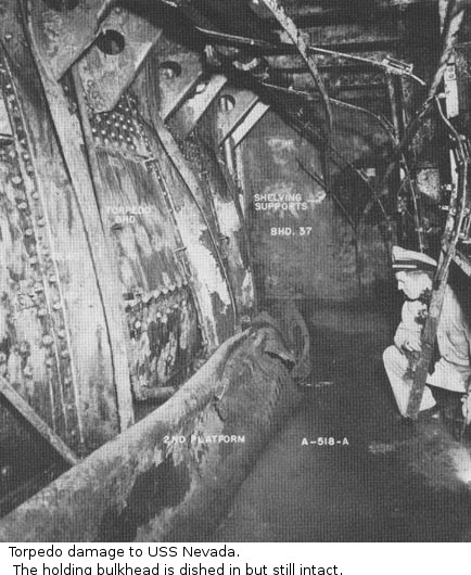
layers. The inner bulkhead of the void layers, known as the
holding bulkhead, provided a final layer of splinter protection
and was typically composed of STS on larger U.S. warships or Type
D steel on larger British or Japanese warships.
The most sophisticated underwater protection systems had multiple
layers of liquid and void spaces, whose transverse bulkheads were
staggered to prevent stresses from being transmitted directly to
the holding bulkhead. The longitudinal bulkheads were designed
with enough clearance to deform and rupture without contacting the
holding bulkhead. Venting plates allowed the hot gases resulting
from the explosion to vent into the air or into noncritical areas
of the ship. The protection system thus could not prevent rupture
of the shell, but it could limit flooding by preserving the
holding bulkhead, which was sufficient to keep the ship in the
fight. Everything outside the holding bulkhead was sacrificial,
being designed to absorb the energy of the underwater explosion
before it could penetrate the holding bulkhead.
American naval architects saw value in the use of skegs to protect the vulnerable propeller shafts from torpedo damage and to permit a wider stern that better protected the aft magazines.
Torpedo protection systems varied in their effectiveness. Branfill-Cook (2014) rates the torpedo protection system of the Tennessee class as among the best but regards the systems used on the Revenge class, which attempted to absorb shock using a large number of sealed horizontal tubes, as almost useless. The torpedo protection on the North Carolinas was good, but the lack of a lower armor belt left the ships vulnerable to diving shells. These were plunging shells that fell just short of the ship and passed through the water with enough remaining energy to penetrate the hull beneath the armor belt. Internal armor belts were particularly vulnerable to diving shells. The South Dakota design remedied this problem by extending the armor belt to the bottom of the hull as part of the underwater protection, but it was discovered that the inflexibility of the armor seriously degraded the performance of the underwater protection system, requiring revision of the liquid loading on the South Dakotas and Iowas. Had they been completed, the Montanas would have had a separate internal belt against diving shells.
Japanese underwater protection systems eschewed liquid loading in
favor of multiple void spaces separated by armored bulkheads,
although the outermost compartment was typically oil-filled and
had some effectiveness as liquid loading. American experts
concluded after the war that the system on Yamato would have
been considerably more effective with more conventional liquid
loading.
Older warships whose original design lacked adequate underwater protection were sometimes retrofitted with torpedo blisters, which were underwater protection systems attached to the outside of the lower armor belt and hull of the ship. These blisters also improved stability by adding significant void space to the beams of the ship. However, because they increased the beam of the ship, they also reduced its speed.
The threat of underwater explosions was a particular problem for cruiser design. Prior to the First World War, cruiser magazines were protected by placing them well below the waterline, close to the sides of the ships, where they were not easily reached by shells. The experience of the First World War showed that such magazines were dangerously vulnerable to underwater explosions, requiring the magazines to be moved closer to the centerline of the ship. This mean greater exposure to shell fire. The more modern cruisers of the Second World War placed the magazines within an armored citadel resembling a scaled-down version of the armored citadel of a capital ship, but many older cruisers included only the machine spaces within their armored citadels, relying on a separate lightly armored box to give some measure of protection to the magazines.
By the end of the war, the U.S. Navy seems to have concluded
that, under the combat conditions that actually prevailed during
the war, the distinction between ships with underwater protection
systems (generally battleships and large carriers) and those
lacking such system was even more important than the distinction
between armored and unarmored ships.
In addition to armor and underwater protection, warship designers
could increase the ability of warships to survive battle damage
through such measures as subdivision, machinery dispersal,
redundant systems, and damage control equipment.
The hulls of warships were subdivided into relatively small
compartments using watertight bulkheads. These contained flooding
from any penetrating hits and were also effective at limiting
spread of fire and smoke. American warships of the First World War
were criticized by British observers for having an excessive
number of watertight doors in their bulkheads, which were likely
to be sprung by hull distortion from battle damage. Later American
warships adopted the British practice of having no watertight
doors at all below the level of the damage control deck, access
being by separate ladders or stairs to each compartment.
Machinery arrangements could substantially increase
survivability. The ideal was for warships to have at least two
engine rooms and two boiler rooms, which were alternated to ensure
that a penetrating hit near a bulkhead could not flood both boiler
rooms or both engine rooms. One of the advantages of turboelectric
drive was that it simplified machinery dispersal.
The stability of a warship was another factor in its survivability. A warship that was designed to strongly resist rolling was also more resistant to capsizing from flooding on one side. However, very stable ships tended to roll so abruptly that gun accuracy suffered, so stability represented yet another trade off in warship design.
The U.S. Navy anticipated that the Iowas could absorb
three torpedo hits with little chance of being sunk (1% chance for
one hit, 2% chance for two hits, and 10% chance for three hits.)
Thereafter the likelihood of sinking rose rapidly, to 40% for four
hits, 70% for five hits, and 90% for six hits. This reflected both
the loss of reserve buoyancy and the likelihood of subsequent hits
striking close to previous hits, where the underwater protection
was already stripped away. The Iowas were considered to
have excellent subdivision, suggesting that the odds of survival
were significantly less for many other large warships.
The distinctive cage masts of older American battleships were
intended to increase the survivability of the observation stations
atop the masts. If an armor piercing shell hit the cage mast, it
would likely pass on through without exploding. A high explosive
shell would detonate, but it would likely destroy only a few
members of the supporting cage. The British preferred sturdy
tripod masts whose legs could be severed only by a direct hit by a
large shell and whose cross-sectional area made such hits
unlikely, and the Americans adopted tripod masts for their modern
battleships and for older battleships undergoing modernization.
The United States deliberately chose to build tanks that were ideal for mass production and would fit into ship cargo holds and landing craft, rather than necessarily be a match for the best enemy tanks. One way of simplifying production was to make armor plating from cast iron, as was done with the Sherman M4 medium tank. Cast iron is very hard and resistant to sudden impact, a desirable quality in armor, but it is also quite brittle, which means that a solid hit is likely to shatter the plate and spray the interior of the tank with fragments. In the Pacific theater, the Sherman was up against Japanese tanks and antitank weapons that were inferior enough that the Sherman's armor protection was adequate. This was not the case in the European theater, where the German Panther and Tiger tanks completely outclassed the Sherman.
Allied combat aircraft
designs often incorporated pilot
armor, self-sealing fuel tanks, and other forms of protection for
the pilot and for vital components of the aircraft. The Japanese
initially eschewed such protection, since it increased aircraft
weight and therefore reduced range, speed, and maneuverability.
However, the Japanese were eventually forced to recognize the
necessity, and most Japanese aircraft designs in production at the
end of the war had pilot armor.
Aircraft armor was typically 0.3" to 0.5" (8mm to 13mm) thick and
was usually face-hardened steel plate. American armor plate was
manufactured from X-7440 nickel alloy. This was capable of
stopping rifle caliber fire, but not a 0.50" (13mm) bullet at
close range and normal impact. However, normal impacts were fairly
unlikely, and the bullet usually had to pass through the aircraft
skin before reaching the plate, which tended to induce tumbling
that reduced penetration considerably. Thus, relatively thin armor
plate provided significant protection against heavy machine gun
fire or even against 20mm cannon fire. Armor was usually placed
behind the pilot to protect him from astern fire, but additional
small armor plates might be placed to protect the pilot from fire
from directly ahead that was not stopped by the aircraft engine.
Additional armor was sometimes placed around critical parts of the
engine, such as the oil pan. American practice was to use lighter
aluminum deflector plates around critical engine parts, which were
designed to deflect bullets rather than stop them cold.
Canopies were often made of bullet-resistant glass. This was
capable of stopping rifle caliber bullets but was not completely
effective against heavy machine gun fire. It also tended to
degrade visibility out of the cockpit, since the heavy glass
required thick canopy supports and it usually introduced greater
optical distortion. Some German fighters had up to 3.5"
(90mm) of armored glass, but 1" (25mm) was more typical.
Self-sealing fuel tanks were initially simply tanks with a layer of rubber on the outside of the tank that would swell when exposed to gasoline, thus sealing small tank punctures. This proved ineffective due to the shock effect of bullets passing through the liquid contents of the tank, which tended to produce large exit holes or even rupture the tank completely. The solution was a tank composed of cells of self-sealing material that had as few seams as possible and were suspended within the wing structure to allow the cells to yield under shock without rupturing. However, self-sealing fuel tanks carried a performance penalty because of their added weight and reduced volume of fuel.
American self-sealing material was built up in seven plies. The
two inner plies were made of Buna-N synthetic rubber backed by
nylon or rayon fabric. Buna-N was unaffected by gasoline and
adhered well to the fabric backing. Next came a ply of
corded fabric saturated with a sealing compound of Buna-S and
natural rubber, followed by two plies of the pure sealing
compound. The sealing compound swelled when it came into contact
with gasoline, quickly and effectively plugging any bullet hole.
The final two plies were heavy corded fabric, the inner saturated
with the sealing compound and the outer saturated with Buna-N. The
outer plies gave the self-sealing material most of its strength
and resilience.
Japanese self-sealing fuel tank designs lagged behind the Allies,
in part because the Japanese were reluctant to accept the
performance penalty. However, as the war went on, the Japanese
were compelled to improve aircraft protection. The simplest
Japanese fuel tank protection, "leak absorbing", was four layers
of natural rubber totaling 3.1mm (1/8") thickness, which was
covered with a layer of kapok and aluminized silk. This proved
almost completely ineffective. "Leak-proofing" was two layers of
heavy crude rubber 12mm (0.47") thick, while "self-sealing" was
six rubber layers 28.6mm (1.125") thick with an inner silk layer
and outer galvanized iron mesh layer. The "self-sealing" tank was
reasonably effective but introduced far too late.
U.S. airmen were equipped with flak suits, which consisted of overlapping plates of manganese steel sewn onto a heavy fabric vest. These reduced low-velocity missile wounds by about 60%.
Ground troops generally did not wear any kind of body armor. The
state of the art in plastics and composites had not advanced to
the point where lightweight body armor was possible, and armor
similar to flak jackets would have so weighed down the troops as
to be counterproductive in fluid combat situations. The Japanese
equipped a few special troops with body armor weighing 9 pounds (4
kg),but this was just 0.08" (2 mm) in thickness and would not stop
even a 0.303" (7.7mm) pistol round at medium range.

Naval
History and Heritage Command #NH 58463
Navy and ground personnel of most nations were equipped with helmets that afforded a measure of head protection. These could deflect a spent or glancing bullet or smaller shell fragments. They were typically made of medium steel rather than any kind of armor plate in order to simplify production.
At the start of the war, U.S. troops used the M1917A1 helmet, a
design dating back to the First World War. The "tin hat" had been
updated with an improved liner and chin strap that made it more
comfortable, but it provided little protection to the neck or
lower head. It was replaced by the M1 helmet by the autumn of
1942. The M1 was made with manganese steel and provided much
better protection, both because it was a harder grade of steel and
because its shape better protected the lower part of the head. The
helmet had a separate liner based on the suspension liners used in
football helmets. This helmet would remain in use until the
Vietnam era.
The British helmet had a similar history. The British started the war with the "Brodie pattern" helmet, which strongly resembled the M1917A1, but by 1944 they had adopted a helmet resembling a cross between the M1917A1 and the M1.
The Japanese used a helmet somewhat resembling the M1 in shape,
but Allied intelligence
officers were unimpressed with the quality of the steel and its
resistance to penetration.
References
"Canada's
Battle in Normandy" (1946; accessed 2011-12-19)
Friedman (1978, 1985)
Garzke and
Dullin (1985)
Geoghegan (2001; accessed 2012-7-19)
Gustin
(1998; accessed 2013-1-19)
"Handbook on
Japanese Military Forces" (1944-9-15)
Lacroix and
Wells (1997)
NAVPERS 16191, "Damage Control" (May 1945; accessed 2019-1-21)
Shaw
(1991; accessed 2011-12-19)
The Pacific War Online Encyclopedia © 2007-2009, 2011, 2014-2016, 2019 by Kent G. Budge. Index