 The Pacific War Online Encyclopedia
|
| Previous: Shiozawa Seisen | Table of Contents | Next: Ships |
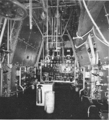
National Archives. Via Wildenberg
(1996)
Ship machinery refers to the boilers and engines that
drive a ship's
propellers, together with the associated pumps, gearboxes,
condensers, and other auxiliary machinery. For most military
planning purposes, the details of the machinery are less important
than the maximum speed of the ship and its fuel consumption curve
(equivalent to its range at various speeds.) The number of shafts
and boilers does have some bearing on the ability of the ship to survive flooding or
other damage to the machinery spaces, propellers and propeller
shafts, and steering. The more, the better, so far as
survivability is concerned.
By the time of the Pacific War, all ships of any
military significance were fueled either with coal, heavy fuel oil, or diesel oil. Coal was widely
used in steam ships at the start of the twentieth century, and it
has the advantage of being found in abundance throughout the
world. However, it is a dirty fuel that produces a considerable
volume of ashes (clinker), and, as a solid fuel, it is difficult
to handle. Coal also produces coal dust, which is a serious
explosion hazard, and Branfill-Cook (2014) has claimed that the
fear of secondary coal dust explosions was one of the motivations
for the Royal Navy to begin switching to oil fuel during the First
World War. Fuel oil burns cleaner than coal without producing
clinker, yields 40% more energy per unit weight, and is a liquid
that is relatively easy to store and handle. However, it is
scarcer than coal. Diesel oil, being more highly refined, burns
cleaner than fuel oil, but is also more expensive. Unlike coal or
fuel oil, which are burned in a boiler to produce steam which is
then fed to an engine, diesel fuel is burned in the engine itself
(which is then known as an internal combustion engine.)
Most of the
warships of the Pacific War burned oil in a boiler to produce hot
steam. The chemical energy released when the fuel was burned was
captured in the steam in the form of heat energy, which imparted
enormous pressure to the steam. This pressure was used to perform
mechanical work, converting part of the heat energy into
mechanical energy to drive the propellers. The engines that
performed this conversion were designed to convert the energy as
rapidly and efficiently as possible, so that the engines could
produce high power without wasting fuel.
The laws of thermodynamics governing steam engines are beyond the scope of this Encyclopedia. It is sufficient to know that it is physically impossible to convert all the heat energy of hot steam into mechanical work. All engines work by tapping a flow of heat energy from a high temperature source (the hot steam) to a low temperature sink (ocean water pumped through a condenser), and at least some of the energy must reach the low temperature sink to maintain the energy flow. The greater the difference in temperature between the source and the sink, the smaller the fraction of the energy flow that must reach the sink and the greater the fraction that can be diverted to do mechanical work. If the high temperature source was three times hotter than the low temperature sink, at least a third of the energy had to make it to the low temperature sink, and not more than two-thirds could be converted to useful work. Thus, the higher the temperature of the steam, the more efficiently its heat energy could be converted into mechanical energy to drive the propellers.
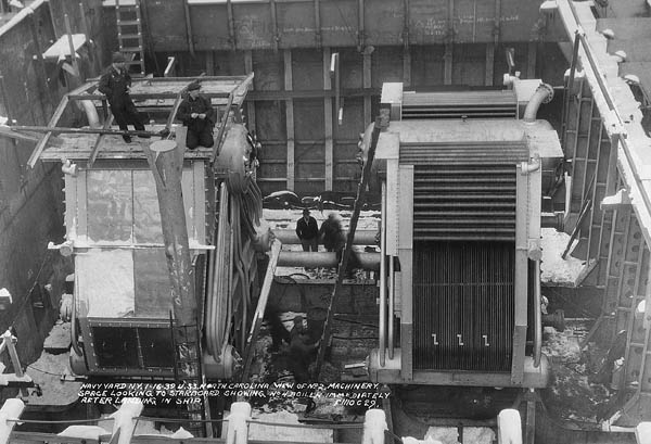
Machnery of battleship North Carolina
under construction. NARA. Via Wikimedia
Commons
Boilers. Modern ships used superheated steam, with a temperature far above the normal boiling temperature of water. Unfortunately, this meant that if battle damage to the machinery allowed the steam to escape, it could kill the engine room crew in seconds. On the other hand, piping stout enough to withstand the pressure of superheated steam proved highly resistant to battle damage, and the high steam temperature made for high efficiency.
Early boilers were often fire tube boilers, also known as Scotch boilers, in which the combustion gases passed through small tubes surrounded by the water to be boiled. However, most warship boilers of the Pacific War were water tube boilers, in which the tubes contained water and were surrounded by the combustion gases. Efficient heat transfer required that the tubes have a large surface area and that there be a large temperature difference between the tubes and the combustion gases. The latter was ensured by bringing the cold feedwater into the top of the furnace, where the combustion gases were coolest, and arranging for the feedwater to pass through progressively hotter parts of the boiler as the water was boiled and the resulting steam was superheated.
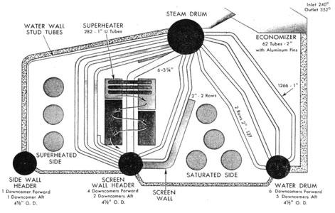
In the most modern boilers of the Pacific War, feedwater
entering the boiler first passed through an economizer, which was
a maze of small tubes located at the top of the boiler, at the
base of the exhaust uptakes. The tubing carried the cold feedwater
past the nearly spent combustion gases, extracting some of their
remaining heat to preheat the feedwater. The feedwater then went
into a steam drum at the top of the boiler. The steam drum had
several large tubes, called downcomers, which carried the water
down to one or more water drums at the base of the furnace.
Two-drum boilers had a single water drum, while three-drum boilers
had two water drums arranged under the steam drum in an inverted
V.
The water drums served as a kind of sump to allow sediments to settle out of the feedwater and and be removed when the boiler was not operating. They also distributed the feedwater into dozens of small tubes that connected the tops of the water drums to the bottom of the steam drum. These tubes were placed directly in the path of the hot combustion gases produced by the burners at the base of the boiler. Most of the conversion of water to steam took place in these tubes, and the mixture of water and steam, being lighter than water alone, rose into the steam drum.
The mixture of water and steam from the water tubes passed through cyclone steam separators within the steam drum, which separated the steam from the water to ensure that water droplets were not carried into the superheater. The steam accumulated in the upper part of the steam drum, and the water level in the steam drum was carefully watched by the engineers to ensure it stayed within design limits.
The steam from the steam drum next passed through another set of tubes to be superheated. At the time of the Pacific War, the superheater usually had its own set of burners that could be independently adjusted to keep the superheated steam within the designed temperature limit. The resulting boiler design was called an "M" boiler because of the arrangement of the tubing.
The boiler was lined with firebrick as an insulator to
prevent excessive heat from escaping into the boiler room, and the
firebrick was often shielded with a set of water tubes forming
what was called a water wall. Forced draft blowers drove fresh air
into the boiler to sustain rapid fuel combustion, and soot blowers
were used to periodically blast superheated steam over the boiler
tubing and remove accumulated soot, which is an excellent
insulator. The boiler piping had numerous manholes and handholes
for inspection and maintenance.
The standard Japanese warship boiler was the Kampon Rō-Gō, which was adopted in 1914. This was a typical small-tube water-tube boiler, capable of producing steam pressures of 427 pounds per square inch (3000 kPa) at a temperature of 662 F (350 C). This compared unfavorably with the Babcock & Wilcox boilers used on contemporary U.S. warships, which achieved a steam pressure of 565 psi (3820 kPa) at 850 degrees Fahrenheit (450 degrees Centigrade) and were significantly more efficient
American machinery was highly standardized, which aided
mass production and
maintenance. The machinery on post-Benson destroyers was so uniform
that a single operation manual was adequate for 331 ships. The
Japanese, by contrast, spread their ship construction over so many
yards that there was little
standardization.
Reciprocating Engines. The oldest warships, as
well as a sizable fraction of auxiliaries and merchant ships, fed
the superheated steam into a set of cylinders with pistons
resembling those of most automobile engines. The pistons drove a
crankshaft that was connected to the propeller shaft. As the steam
drove the piston, converting heat energy into mechanical work, the
steam rapidly cooled, and the resulting temperature fluctuations
in the piston and cylinder wasted energy. To improve efficiency
and increase power, the steam usually passed through a set of
three cylinders. Each extracted only part of the energy, reducing
the temperature fluctuations and the resulting energy loss. These
so-called triple-expansion reciprocating engines were still
relatively inefficient, converting less than 30% of the heat
energy into mechanical work; they were noisy and produced heavy
vibrations; and they took up a great deal of space. Each stage had
to be considerably larger than the preceding stage, so quadruple
expansion was employed only on torpedo craft where speed was at a
premium, and quintuple expansion was out of the question. Most of
the warships of the Pacific War used turbine engines instead.
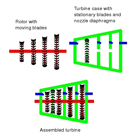
Turbine Engines. A turbine engine consists of a
rotor mounted in a heavy outer casing. Attached to the rotor are a
set of disks, each of which carries a set of blades that somewhat
resembles a large fan. These are known as moving blades. The case
also has sets of blades mounted in its interior that are known as
stationary blades.
A turbine typically has several stages, or sets of
blades, each of which extracts part of the heat energy of the
steam. These stages typically increase in diameter in the
direction of the steam flow, allowing the steam to expand as it
moves through the turbine. There are several distinct types of
turbine stage, corresponding to efficient operation at different
pressure levels.
A modern warship typically had three or four turbines on
each shaft. At a minimum, there was a high-pressure turbine, a
low-pressure turbine, and an astern turbine. There might also be a
cruising turbine. The astern turbine was often installed in the
same turbine case as the low-pressure turbine, while the cruising
turbine was often installed at the front of the high-pressure
turbine. During normal cruising, steam passed from the boiler
through the cruising turbine, then the high-pressure turbine, and
finally the low-pressure turbine before entering the condenser,
returning to the liquid state, and being pumped back to the
boiler. When maximum power was required, the cruising turbine was
bypassed, so that steam passed directly from the boiler to the
high-pressure turbine. This gave maximum power at a significant
cost in efficiency. The direction of propulsion could be reversed
by feeding the steam directly to the astern turbine.
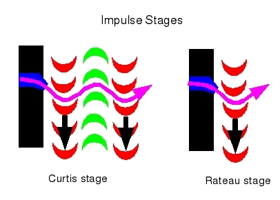
The high-pressure turbine usually began with one or more
Curtis stages. A Curtis stage consists of a nozzle diaphragm, a
set of moving blades, a set of stationary blades, and a second set
of moving blades. Steam passing through the nozzle is accelerated
to a high velocity while losing pressure, as part of its heat
energy is converted to kinetic energy (energy of motion). The jet
of fast-moving steam strikes the first row of moving blades,
losing velocity as part of its kinetic energy is transferred to
the blades, which turn the rotor. The steam "ricochets" off the
first set of moving blades into the stationary blades, which
redirect the steam back at the second set of moving blades. Here
the steam again loses velocity as it transfers kinetic energy to
the second set of blades and from there to the rotor. Because heat
energy is converted to kinetic energy only in the nozzle, and not
in the blades, the Curtis stage is classified as an impulse stage.
Typically the entire high-pressure turbine is composed of impulse
stages, separated from one another by nozzle diaphragms.
The final stages of the high-pressure turbine are
typically Rateau stages. These are very simple stages consisting
of a nozzle diaphragm and a single set of moving blades. Like the
Curtis stage, the Rateau is classified as an impulse stage.
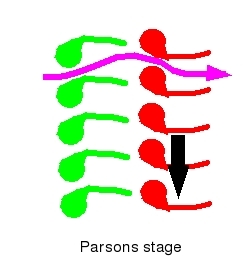
The low-pressure turbine typically consists of several sets of
Parsons stages. The Parsons stage is classified as a reactive
stage rather than an impulse stage, because the blades themselves
convert heat energy to kinetic energy rather than relying on a
separate nozzle to perform this function. This is more effective
at lower steam pressures than an impulse stage. The Parsons stage
consists of a set of stationary blades followed by a set of moving
blades, all shaped like tiny airfoils. Steam passing over the
stationary blades is accelerated as its pressure drops. The steam
then passes over the moving blades, creating "lift" and losing
both pressure and velocity as its thermal and kinetic energy is
transferred to the blades.
When space was at a premium, the low-pressure turbine was split
into two halves facing each other inside the turbine case.
Turbine engines operate best at high rotation speeds.
This requires very large turbines if the rotor is connected
directly to the propeller shaft, since propellers do not function
well at very high rotation speeds. The alternative is to use
smaller turbines operating at very high speed and connected to the
propeller shaft through a complicated reduction gearbox. The
majority of warships that saw service in the Pacific War used
these geared turbine engines.
Well-designed turbines could achieve 40% efficiency. This is close to the practical limit of turbine technology: The 50% efficiency barrier remains unbroken at the start of the 21st century.
Japanese Kampon geared turbines were excellent engines,
delivering as much as 40,000 shp. This was slightly greater than
the power output of the Westinghouse geared turbines on the Essexes, but
inferior to the 53,000 shp delivered by the General Electric
geared turbines of the Iowas.
British machinery of the Second World War was surprisingly poor,
and Brown (2000) has commented that British machinery
manufacturers attempted to compensate for poor design with
excellent workmanship.
Condensers and Feed Water Conditioning. Turbine engines were carefully designed so that the steam leaving the low-pressure turbine was just above its condensation temperature, since any moisture droplets in the steam would rapidly erode the turbine blades. This spent steam was directed into the main condenser, which was a large tank containing numerous small tubes through which cold seawater from outside the ship was pumped. The seawater absorbed the remaining heat in the steam, carrying it out of the ship, and the steam condensed back into liquid water, which collected in a hot well at the base of the condenser. The condensation of the steam produced a partial vacuum that drew the spent steam from the low-pressure turbine without the need for any other pumping arrangement.
This water was then pumped into an air ejector to remove
any air or other gases, then into a deaerating feed tank. Here the
condensate was rapidly heated to just below its boiling point,
which drives any dissolved oxygen out of the condensate. The
oxygen would otherwise cause rapid corrosion in the boiler and
engines. The condensate was now ready to be used as feedwater to
the boiler` to complete the cycle. It was pumped to the boiler
using pumps capable of moving the water against the high pressure
in the boiler.
A number of American battleships and aircraft carriers were equipped with turboelectric drive. Instead of driving the propellers directly, the turbines drove large electrical generators. The electrical power was then bussed to large motors that drove the propeller shafts. This eliminated the need for reduction gearing and allowed the machinery to be spread out over a larger number of compartments, improving subdivision. It allowed considerable flexibility in how the engines were operated. Some of the carriers with turboelectric drive could even be propelled astern at full power, allowing flight operations to take place in either direction of the flight deck. There was some energy lost in the conversion from mechanical to electrical and back, but since electrical generators and motors could be designed with better than 85% efficiency, this was not critical. However, turboelectric drives were very heavy (though also very compact), and with displacements limited by treaty from 1922 on, American warship designers largely abandoned turboelectric drive in favor of reduction gearing. This was fortunate, as turboelectric drive proved to be less robust than expected under battle conditions,
Although diesel fuel is more expensive than fuel oil, and diesel engines have some of the faults of reciprocating steam engines, a well-designed diesel engine could achieve efficiencies approaching 60%. As a result, smaller warships requiring long cruising ranges were equipped with diesel engines. However, the diesel engines of 1941 were relatively bulky and were considered unsuitable for high-speed warships. Improvements in turbocharging would lead to widespread adoption of diesel engines in postwar warships.
Diesel engines are internal combustion engines, similar in many respects to aircraft engines, but using diesel fuel in place of gasoline. Diesel fuel is less volatile than gasoline and, in 1941, it was also less expensive. The relatively low volatility of diesel fuel allows very high compression ratios, which gives the engines their high efficiency and also eliminates the need for spark ignition. Diesel fuel is injected directly into the extremely hot air in the cylinder at maximum compression,and the hot air ignites the fuel.
Submerged submarines require a source of power for propulsion that is independent of atmospheric oxygen. Nuclear power was in its infancy during the Pacific War and would not be used for submarine propulsion until long after the war was over, and, while the Germans experimented with compressed oxidizers such as hydrogen peroxide (the Walter engine), the usual source of power for underwater propulsion was large banks of lead-acid batteries. These used metallic lead as the fuel and lead dioxide as the oxidizer. Lead-acid batteries were heavy and bulky, but could produce a high electric current with which to run electric motors driving the propeller shafts. Their most serious drawback was that they were quickly exhausted, rarely allowing a boat to remain submerged for longer than 24 hours. This meant that all but a few midget submarines also required conventional engines, both for surface propulsion and to drive generators with which to recharge the batteries.
The conventional engines on almost all submarines of the
Pacific War were diesel engines. The most advanced submarines used
diesel-electric engines, which were similar to turboelectric
engines in that the engines were used to drive generators whose
power was then bused to electrical motors that drove the propeller
shafts. Not only did this simplify the machinery layout, of
particular importance in submarines, but it gave the submarine
commander full flexibility to use any number of his engines for
surface propulsion while using the remainder to recharge batteries
or bringing them offline for maintenance. A commander could even
heave to and use all his engines to recharge batteries if this
seemed advisable.
The power generated by a turbine engine was
usually expressed as the shaft horsepower or SHP, which is the
power delivered to the propeller shafts. Indicated
horsepower or IHP was the preferred power measure for
reciprocating engines; it was determined by directly measuring the
pressure in the cylinders during the engine stroke and summing up
the product of pressure and stroke distance. It ignored losses due
to friction in the cylinders or further down the drive train.
Brake horsepower or BHP was commonly used for diesel engines. It
was determined by directly measuring the torque and rotational
speed delivered by the engine and summing up their product. It
took into account friction within the engine but not losses
further down the drive train.
The power actually delivered to the water for propulsion was the effective horsepower or EHP, usually about 50% of the SHP for a well-designed propeller.
References
Alden (1979)
Federation of American Scientists (accessed 2009-2-3)
Friedman (1978, 1985)
Lacroix and
Wells (1997)
U.S.
Naval Technical Mission to Japan (1946-4; accessed 2013-7-17)
The Pacific War Online Encyclopedia © 2009, 2013-2015 by Kent G.
Budge. Index