 The Pacific War Online Encyclopedia
|
| Previous: Aircraft Carriers | Table of Contents | Next: Aircraft Pilots |
The aircraft
engines of the Second World War were almost exclusively piston
engines using high-octane gasoline
(petrol) fuel. Jet engines were introduced towards the end of the
war in Europe, but saw no operational use in the Pacific. Rocket engines were employed by
the Japanese MXY7 Ohka suicide aircraft.

The heart of a piston engine was a set of cylinders, each containing a piston. The pistons were attached by piston rods to a central crankshaft through one end of the cylinder, and the other end of the cylinder was tightly sealed except for a set of valves and spark plugs. The pistons invariably operated on a four-stroke or Otto cycle. During the first stroke, the piston was pulled downwards by the crankshaft as the fuel valves opened to allow a mixture of air and gasoline vapor to enter the cylinder. During the second stroke, the valves closed and the piston began to move back up (still driven by the crankshaft) and the air and vapor mixture became highly compressed. As the piston reached the top of the cylinder, the spark plugs fired and ignited the fuel-air mixture, whose pressure increased enormously as it burned. During the third stroke, this white-hot gas drove the piston back down the cylinder with great force, driving the crankshaft. During the fourth stroke, the exhaust valves opened as the crankshaft pushed the piston back to the top of the cylinder, expelling the burned fuel and air. The cycle was then ready to repeat.
The timing of this cycle had to be carefully designed, and the engine had to efficiently feed fuel-air mixture to the cylinders and efficiently carry off the exhaust. The fuel-air mixture needed to be at a high enough pressure to force it rapidly into the cylinders, while the exhaust system needed to be at low enough pressure for the exhaust to be rapidly extracted from the cylinders. The combustion process created tremendous amounts of heat, of which only a fraction (typically 20% to 30%) was used to drive the piston. Much of the remaining heat was carried off in the exhaust, but the rest went into heating the cylinders, which had to be cooled to prevent overheating. The cylinders could be cooled either by fitting them with large cooling fins and directing a strong flow of air over the fins (air cooling) or by surrounding them with a jacket containing water or a mixture of water with ethylene glycol (liquid cooling.) In the latter case, the liquid still had to be circulated to a radiator exposed to air flow, so in some sense liquid cooling involved an extra step. However, the radiator could be located some distance from the cylinders, which gave added design flexibility.
|
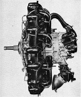
An Ha-40 inline aircraft engine. U.S. Navy. Via Francillon (1979) |
|
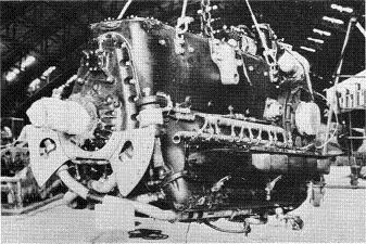
 A Kotobuki 1 KAI 1 radial aircraft engine. U.S. Navy. Via Francillon (1979) |
Because the piston drove the crankshaft during only one of the four strokes, high-performance engines required several cylinders firing in sequence to ensure that at least one piston was driving the crankshaft at all times. There were many ways that the cylinders could be arranged around the crankshaft, but the high-performance piston engines of the Second World War fell into two broad categories. Inline engines typically placed the cylinders in long rows, rather like an automobile V engine. Radial engines arranged the cylinders in one or more circles around the center of the engine. Inline engines had a much smaller cross-section, which simplified streamlining; however, the inline cylinder layout could not be adequately cooled by airflow alone, so a liquid cooling system was required. Radial engines had a large cross-section, but with appropriate cooling fins, the cylinders could be cooled by airflow alone. The tradeoff was greater drag for the radial engine versus greater weight and vulnerability to damage for the inline engine. In practice, the tradeoff of weight for drag meant that neither the radial or inline engine gave a decisive advantage for aircraft speed. The inline-engine Mustang was very fast, but so was the radial-engine Corsair. The inline-engine Spitfire was nimble, but so was the radial-engine Hellcat. The type of engine was a key recognition feature for single-engine monoplanes: Aircraft employing radial engines had a blunt nose due to the large cross-section of the engine, while aircraft employing inline engines had a pointed, streamlined nose to take maximum advantage of the reduced engine cross-section.
Multi-row radial engines were developed as early as the First
World War, but this engine configuration posed the challenge of
providing adequate cooling for the second row of cylinders.
However, the introduction of the Pratt & Whitney R-1830 Twin Wasp
in 1932 proved that such engines were viable, and the Twin Wasp
became one of the most produced engines in history.
To a point, larger cylinders delivered greater power. However,
the length of a cylinder was limited by the inertia of the piston
rod, and the diameter of the cylinder was limited by the speed at
which the burn front ignited by the spark plugs could propagate
across the cylinder. The aircraft engines of the Second World War
had two sparks plugs on opposite sides of each cylinder, but even
then the cylinder diameter was limited to about six inches (15
cm). The spark plugs were wired independently, and it was
accepted practice for pilots to switch off one half of the
ignition system and then the other half while warming up the
engine, to detect any faults in either ignition system.
Aircraft fuel systems could be quite complicated, but at a minimum a fuel pump was required to pump the fuel from the tanks through a filter and into a carburetor, in which a flow of air sucked fuel from a float chamber and rapidly converted it to vapor, which then entered the engine. More sophisticated engines sprayed a fine jet of fuel into the incoming air stream or even injected the fuel directly into the cylinder at the appropriate moment, though direct injection required extremely high manufacturing tolerances to ensure that exactly the right amount of fuel was injected at just the right moment. Fuel injection did have the important advantage over float carburetors that the latter could not function at negative gravity arising during violent combat maneuvers. Air normally entered the engine through a forward-facing ram inlet that allowed the aircraft's own forward motion to help force the air into the engine, while the exhaust was expelled to the rear of the aircraft and provided a small amount of added thrust.
The moving parts of the engine required constant lubrication, which was provided by oil pumped to the appropriate points. The pump was invariably an intermeshing gear pump, which was ideal for imparting very high pressure to a viscous liquid at a modest flow rate. The oil was cooled after it had circulated through the engine and was filtered before being returned to the oil pump.
Most engines used poppet valves in their cylinders, as shown in the preceding animation. These looked something like a golf tee and were seated in a very hard, durable ring of Stellite. The valves were subject to intense heating, and so their hollow stem contained a small quantity of metallic sodium to help carry away the heat. However, a small number of aircraft engines used during the Pacific War used sleeve valves, which took the form of a separate metal sleeve between the piston and the cylinder which slid or rotated to open ports at the appropriate points in the engine cycle. Sleeve valves operated relatively quietly and were highly reliable and efficient, but they tended to burn large quantities of oil, because of the additional surfaces requiring lubrication.
As a aircraft gained altitude, the reduction in air pressure
improved exhaust efficiency while hindering carburetor efficiency.
At higher altitude, the loss of carburetor efficiency predominated
and the engine rapidly lost power. To regain high altitude
performance, it was necessary to equip the engine with a
supercharger, which was a centrifugal air pump that helped drive
air into the engine. Conventional superchargers were driven by the
crankshaft at an enormous rotation rate, typically 30,000
rotations per minute, through a set of multiplying gears. This
required an elaborate clutch to avoid stripping the gears when the
engine power fluctuated. The most sophisticated superchargers had
up to three speed settings for different situations. A more
sophisticated form of supercharger was the turbocharger, which
used the engine's own exhaust to drive the supercharger.
Turbochargers were highly effective at high altitude but required
scarce alloying metals such as tungsten
to manufacture turbocharger blades that could stand up to the
extremely hot exhaust gases. As aircraft designers sought ever
greater high altitude performance, most large military aircraft
engines began to be equipped with two turbochargers. The high
degree of compression achieved this way heated the incoming air
sufficiently that an intercooler (between the two turbochargers)
or an aftercooler (after the second turbocharger) or both were
required. Production of turbochargers was a significant constraint
on aircraft production throughout the war.
Many high-performance engines had a takeoff or combat boost
setting to provide maximum power for a limited period of time.
During combat boost, the supercharger ran at its maximum rate and
the fuel-air mixture entering the engine was made unusually rich.
The rich mixture suppressed predetonation and helped cool the
engine. Some engines included injection of water or of a
water-methyl alcohol mixture into the cylinders during combat
boost, resulting in a boost setting that as much as doubled the
power over maximum normal engine operation. However, combat boost
could be maintained for only a few minutes without risking the
destruction of the engine, and the pilot then had to switch to
rated boost, which was the maximum power that could be maintained
continuously.
The engine turned a propeller, whose blades had a simple airfoil
shape, often that of the Clark Y airfoil. The rotating blades
drove air from in front of the propeller to its rear, and this
acceleration of a large volume of air was matched by an equal and
opposite force on the propeller which drove the aircraft through
the air. Because the blade rotated more slowly at the center
than at the end, the blade had to be manufactured with a twist so
that the angle of attack of the blade was greater at the center
than at the tip. This ensured that the blade tip remained subsonic
while allowing the inner blade to drive a strong flow of air. Most
propellers of the Second World War were variable pitch propellers,
of which the most sophisticated was the constant speed propeller.
A constant speed propeller had a complicated control mechanism
that automatically increased the pitch as the engine was throttled
up, so that the engine maintained a constant number of rotations
per minute as the propeller "bit" harder into the air at higher
power. In case of engine failure, the propeller could be
"feathered", that is, the blades could be rotated directly into
the air flow to minimize air resistance and prevent the blades
from "windmilling" and possibly further damaging the engine. The
blades could usually also be reversed to slow the aircraft after
landing. A propeller typically had at least two blades, for
balance, but propellers on some of the highest-performance
aircraft used during the war, such as the Spitfire XIV, had as many as
five blades. The crankshaft might be connected directly to the
propeller hub, but since the ideal rotation rate for the engine
was often greater than the ideal rotation rate for the propeller,
it was common for the crankshaft to connect to the propeller hub
through a set of reduction gears.
While many aircraft of the 1940s used electric starters to start
their engines, military aircraft favored cartridge starters, which
used large cartridges of gunpowder.
The gas from the cartridge pushed a piston whose motion was
converted to torque to turn the engine. The engine had to be
strengthened to take the powerful kick it got from the cartridge,
and the cartridges themselves were somewhat expensive, but they
were a lightweight self-contained starting system ideal for use at
forward airfields.
The aircraft engines of the Pacific War relied on high-octane
aviation gasoline. The high octane rating meant that the fuel had
very little tendency to predetonate when compressed by the piston
in the cylinder. This in turn meant that high compression ratios
could be used, which increased engine power. The use of
high-octane gasoline posed logistical
challenges, since it was expensive and hazardous to transport and
store, and because aircraft consumed fuel at a prodigious rate.
A quirk of both Japanese (Goodwin and Starkings 2017) and British
(Bergerud 2000) aircraft engine design was that no great effort
was spent on eliminating all oil leaks. It was considered more
cost effective to simply replace leaked oil after each sortie. In
the case of the Japanese, the acceptance of oil leaks was so
extreme that some aircraft, such as the D3A Val, were notorious for
obstructed vision from oil leakage onto the windscreen.
All of Japan's aircraft engines were imported or built under license until the mid-1930s, and the Japanese designs in production when war broke out in the Pacific were based on foreign designs. Almost all were air-cooled radial engines, and some were quite good. While the Japanese made no great technological breakthroughs, they were innovative in perfecting existing designs and technology. American experts who examined Sakae and Kinsei engines in aircraft wreckage at Pearl Harbor described them as "like a Swiss watch", comparing their workmanship favorably with Allied aircraft engines. However, Japan was cut off from the remarkable advances in metallurgy made in the United States during the war years, and important alloying metals were in very short supply. Japanese engineers were too few in number and worked under a stifling military bureaucracy. As a result, the performance of Japanese aircraft engines lagged badly behind those of her principal enemy as the war dragged on.
One reflection of this is the government regulation of Mitsubishi, one of the largest of the zaibatsu or family industrial conglomerates and a major manufacturer of aircraft and aircraft engines. The steel import supply chain of Mitsubishi was taken over by the Japanese government in 1938. Together with poor control of hundreds of subcontractors feeding parts into the production lines, this significantly hinder productivity. The Airplane Industry Manufacturing Law of August 1938 put all aircraft manufacture under government license, apparently to encourage lesser players the expense of the zaibatsu (Mitsubishi, Sumitomo, Kawasaki, Nakajima, and the Nissen division of Hitachi). By May 1939 the major aircraft engine manufacturers were Aichi, Ishikawajima, Gasuden, Kawasaki, Mitsubishi, and Nakajkima. Gasuden had largely dropped out of aircraft engine manufacture by the time war broke out in the Pacific. Propellers were manufactured by Japan Musical Instrument Company and Sumitomo. By this time, the government controlled the component supply chain to the major manufacturers.
By May of 1943 it had become clear that the Army and Navy had to cooperate better to make good use of the scarce resources available to Japan. The two-digit Joint Designation System for aircraft engines was adopted that month. The first digit indicated the general engine type, while the second digit indicated cylinder bore diameter and stroke distance. Manufacturer and precise model number were also part of the designation. Thus, the Nakajima [Ha-35] 25 engine was an air-cooled 14-cylinder double-row radial engine (3) with a bore of 130mm and stroke of 150mm (5) designed by Nakajima, model number 25.
Ha-1: air-cooled inline engine
Ha-2: air-cooled single-row radial engine
Ha-3: air-cooled 14-cylinder double-row radial
engine
Ha-4: air-cooled 18-cylinder double-row radial engine
Ha-5: air-cooled, more than 18-cylinder, multi-row radial engine
Ha-6: liquid-cooled 12-cylinder engine
Ha-7: liquid-cooled, more than 12-cylinder, engine
Ha-8: diesel engine
Ha-9: special engine
...1: 140/130
...2: 150/170
...3: 140/150
...4: 140/160
...5: 130/150
...0: 130/160
In practice, a bewildering variety of nonstandard designations were used for Japanese aircraft engines. Designations such as Ha-26-I should not be confused with [Ha-26] 1 which are different engines.
On 1 November 1943, the Japanese government created a Ministry of
Munitions to further coordinate manufacture, and there were some
improvements. Engine manufacture rose from 28,500 in 1943 to
46,500 in 1944. However, a major earthquake on 7 December 1944,
combined with fears of the Allied strategic bombing
campaign, produced a near-panic and enactment of hte
Urgent Dispersal of Plants Act of February 1945, which seriously
disrupted manufacture. Aircraft engine manufacture dropped to just
11,900 from January to August 1945, more from the crash effort at
dispersal than from bomb damage.
Japanese aircraft engines were subjected to a run-in of 7 hours
by the Army and 9 by the Navy before being certified for use.
About 10% of engines failed. Lack of fuel and test stands reduced
these numbers to 1.5 hours and 2 hours, respectively, by the end
of the war, with corresponding loss of reliability.
U.S. aircraft engine design made rapid strides during the war,
primarily due to improvements in metallurgy that made it possible
to make lighter, smaller, more powerful engine components. The Allies also had access
to more reserves of crucial alloying elements such as tungsten for
turbocharger blades.
U.S. aircraft engines typically had an official designation consisting of R or V for radial or inline engines, respectively; the approximate displacement in cubic inches; and a model number. Some had a popular nickname as well. Thus, the Pratt & Whitney R-2800 Double Wasp was a radial engine with an approximate displacement of 2800 cubic inches (46 liters) which came in several models, such as the R-2800-8W with water injection.
The leading American aircraft engine manufacturers in 1941 were Wright and Pratt and Whitney,
with Allison just coming into the
picture as a major manufacturer of inline engines. However, by
1944, some 60% of engine horsepower was being produced by former
automobile manufacturers under license.
SR-1340
Wasp
R-985 Wasp Junior
R-1535 Twin Wasp
Junior
R-1820 Cyclone
R-1830 Twin Wasp
R-2600
Cyclone
14
R-2800 Double Wasp
R-3350 Duplex
Cyclone
V-1650
Packard-Merlin
V-1710 Allison
Hercules
Mercury
Pegasus
Perseus
Taurus
References
Goodwin and
Starkings (2017)
Gunston (1999, 2006)
The Pacific War Online Encyclopedia © 2006-2007, 2009-2010, 2012-2013, 2019 by Kent G. Budge. Index