 The Pacific War Online Encyclopedia
|
| Previous: Ship Machinery | Table of Contents | Next: Shipyards |
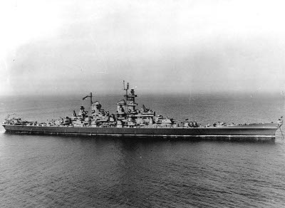
National
Archives
#80-G-453313
Ships are complex systems, the detailed description of
which is beyond the scope of this Encyclopedia. Furthermore, even
ships of the same class tended to show small variations, and most
ships were extensively modified as the war progressed. In
particular, both the Allies
and the Japanese tended to add
more antiaircraft
protection and more sophisticated radars
to a ship every time it was refitted. Ship specifications given in
this Encyclopedia are therefore nominal values at the time ships
of the class were first committed to the Pacific.
Warships of the Second World War benefited from a number
of improvements in engineering from the First World War. One was
improved metallurgy. High-strength steels gave the same
strength as older steels with less weight. Superior framing
methods and the use of welding are estimated by Friedman (1978) to
have reduced hull weights 18% between 1906 and 1942. Superior
alloys for turbine blades made it possible to run ships' machinery at
higher temperatures and pressures, yielding more power with
greater efficiency. Armor was
also superior in quality.
Another area of improvement was in hull forms. All the
major naval powers did extensive testing of hulls in model basins.
Curiously, American
tests demonstrated such advantages to twin-skeg hulls that they
were used in almost all major U.S. warships built during the war,
including all post-treaty battleships,
while British and Japanese model basin tests
incorrectly predicted that twin skegs would be counterproductive.
Welding began to replace riveting in ship construction
between the wars. Rivets required overlapping plates, and a
riveted joint did not have the strength of the solid plate. Welds
eliminated the need for overlapping plates, thereby reducing
weight, and a properly welded joint was as strong as the original
metal. This was particularly important in underwater protection
systems and in submarine
hulls, which had to withstand enormous hydrostatic pressure
without leaking. Welding was also much less labor-intensive than
riveting: Riveting was done by teams of four men, while welding
could be performed by a single welder, or even automated using
welding jigs. On the other hand, welding was a relatively new
technology and properly welded joints were still difficult to
achieve. Riveted joints had the advantage that they tended to halt
the propagation of cracks.
Finally, tremendous advances were made in naval electronics, particularly radar, which transformed naval warfare.
Between the wars, the Japanese Navy General Staff was determined to make Japanese ships unit-for-unit superior to those of any other power. This led to a tendency to load down Japanese warships with an excessive weight of weapons systems and other equipment. However, Tomozuru capsized in a typhoon in 1934, and the chief Japanese warship designer, Fujimoto Kikuo, was sacked. The Tomozuru Incident was followed in September 1935 by the Fourth Fleet Incident, in which a force of 58 ships on maneuvers encountered another typhoon and many ships were severely damaged. These led to the reconstruction of many Japanese ship classes, and the Japanese had a very seaworthy fleet by 1941.
Displacement.
The usual measure of the overall size of a warship was its
standard displacement, which was the total weight of the ship
exclusive of fuel and feed water, measured in long tons (1.016
metric tons), when loaded for combat. Standard displacement was
largely a creation of the naval
disarmament treaties, since it was the measure used to
determine if a warship was within the negotiated tonnage limits.
For merchant vessels, the usual measure was either the gross
register tonnage (G.R.T.) or the deadweight tonnage. G.R.T. was
the total volume of the ship in units of 100 cubic feet (2.83
cubic meters). Deadweight tonnage was the maximum weight, in long
tons, of crew, passengers, and cargo that the ship could safely
carry. In some cases merchant ships are described by light and
fully loaded displacement; the deadweight tonnage would be
slightly less than the the difference between these two
displacements.
Dimensions.
These are given as the overall length, beam (width), and draft
(maximum depth of the keel). For operational purposes, draft was
most important, as it determined how closely a warship could
approach shore, and deep-draft vessels could not enter the
shallowest harbors. U.S.
warships were long restricted to a maximum draft of 23'6" (7.2m)
to ensure they could cross the bars at the mouths of important
ports in the southern United States. Beam theoretically could have
limited passage through the Panama
Canal, but for this very reason all U.S. warships launched
before and during the war were designed to fit through the Canal.
The ratio of length to beam was one of the factors
determining maximum speed (the greater the ratio, the faster the
ship, up to a value of about 10). The critical parameter for
evaluating ship speed is the Froude number, defined as V/sqrt(gL)
where V is the velocity, L the ship length at the waterline, and g
the acceleration due to gravity. Ship designers of the early 20th
century used the "speed-length ratio", defined as V/sqrt(L) with L
in meters and V in knots, which is obviously proportional to the
Froude number. The critical speed-length ratio at which the power
required to achieve a given speed began to sharply increase was
around V/sqrt(L) = 1.4 to 1.6, corresponding to a Froude number of
about 0.24 to 0.27. A fast ship was one whose speed-length ratio
at maximum speed was greater than about 1.8 A Fletcher-class destroyer had a maximum
speed-length ratio of about 3.3, a Baltimore-class cruiser
had a maximum speed-length ratio of about 2.3, an Essex-class carrier or Iowa-class battleship
had a maximum speed-length ratio of about 2.0, a Nevada-class
battleship had a maximum speed-length ratio of about 1.5, and a Liberty Ship had a
maximum speed-length ratio of about 0.95.
One measure of the strength of a hull was the girder
ratio, which was the ratio of the length of the ship to the
distance between the keel and the strength deck. The lower the
ratio, the smaller the stresses on the hull. The strength deck was
usually the highest deck that was continuous along the length of
the ship. The Nelsons
had an unusually low ratio of 13:1 that allowed lighter
construction, and the American fondness for flush weather decks on
destroyers (which thus were also the strength decks) meant unusual
strength, though at the expense of poorer seakeeping. The Japanese
adopted undulating decks on some warships as an attempt to have
the weather deck serve as strength deck without sacrificing
seakeeping.
Maximum speed. This is the maximum speed the ship could sustain for any length of time.
Speed was a function not only of machinery power, but of
hull length, hull wetted area, and hull form. Length was the
single most important factor in reducing the power needed to
achieve a given speed, since the further apart the bow and stern
were, the less interference there was between waves generated at
each end of the ship. Next in importance was the prismatic
coefficient, CP, which was the ratio of displacement to the volume
of a prism of length L and area equal to the maximum underwater
cross section of the hull. The ratio of beam to draft, B/T, was
also important. Best hull efficiency was achieved for small CP and
B/T, that is, a full, deep underwater hull form. However, low B/T
reduced stability, so naval architects chose a B/T between 3 and
3.8 for capital ships and CP varying from 0.5 at a speed ratio
below 1.6 to 0.65 at a speed ratio of 3.0. A capital ship could
achieve the desired CP with square bilges, but a destroyer
required rounded bilges, which helps explain the tendency of
destroyers to roll badly.
The U.S. Navy discovered through experimental work in model basins that a bulbous bow significantly improved efficiency at a speed ratio of about 1.8. Thus fast American capital ships, whose speed ratio was near this figure, all had bulbous bows, while cruisers and destroyers did not.
Stability was determined largely by the metacentric
height, GM, which was the distance between the center of gravity
and the metacenter. The metacentric height depended on hull form
but was generally greater for ships with larger B/T. The ideal was
about 5 feet or 1.5 meters for a large ship. It was possible for a
ship to be too stable, leading to a fast, uncomfortable
roll that was detrimental to gunnery. This seems to have been a
fault of the American destroyer escorts.
Complement. This is the nominal size of the ship's crew. This number tended to go up as the war progressed.
Aircraft. This gives the length of the flight deck, the number of elevators and catapults, and the maximum number of aircraft a carrier could reasonably operate. Most carriers could carry more aircraft, but could not make effective use of them. For other classes of ships, this specification gives the number of seaplanes and seaplane catapults, if any.
Armament. This is the typical armament of the class at the time that ships of the class were first committed to combat in the Pacific. Most ships upgraded their antiaircraft armament once or more during the war. Main armament was rarely upgraded without reclassification of the ship.
Protection.
Describes the armor protection of the ship. In general, only a
portion of an armored warship (called the citadel) was protected.
The citadel typically consisted of belts of armor on the sides of
the ship, enclosed on top by one or more armored decks and at the
ends by armored bulkheads, plus armor protection for the main gun
turrets and the conning tower.
Not listed is the general toughness of the ship, which
is difficult to quantify. American warships often used Special
Treatment Steel (STS) for internal structural members and
bulkheads, which was resistant to splinters. The British and
Japanese likewise used Type D Steel. Other navies probably did
something similar. Toughness also depended on sound design, and it
was not strongly correlated with the quality of the armor system.
Some unarmored destroyers were quite tough for their size, while
the heavily armored Yamatos appear to have
had significant structural weakness, if the difficulty of
satisfactorily repairing torpedo
damage is any indication.
Machinery. Gives the type of machinery, the number of shafts and boilers, and the total shaft horsepower.
Multiple shafts were required for high-speed ships, since only so much power could be efficiently transmitted to the water by a single screw. The Americans preferred four shafts on their carriers, cruisers, and fast battleships, with twin rudders behind the inboard propellers which gave excellent maneuverability. The inboard and outboard propellers had five and four blades each, which reduced resonance vibration. Older battleships and destroyers had twin screws, and the Allen M. Sumner class was the first fleet destroyer to have twin rudders, although American destroyers escort all had twin rudders, since maneuverability was critical for antisubmarine warfare. Japanese and British practice were generally similar, with the use of triple screws being a peculiarity of German naval architecture.
The number of shafts also had some bearing on the ability of the ship to survive flooding, since multiple shafts allowed better machinery dispersal.
Bunkerage. This specifies the amount and type of fuel carried by the ship. It is important in determining refueling requirements. The amount of aviation gasoline carried by aircraft carriers and (when known) seaplane-carrying vessels is also listed.
Range. This is
given as the maximum distance that the fully fueled ship could
travel at its designed cruising speed before refueling. Some
sources quote lesser ranges and higher speeds, indicating that the
ship rarely operated at its designed cruising speed. This was
particularly the case for lighter escort vessels (cruisers and destroyers.)
Most warships consumed fuel prodigiously at maximum speed. Merchantmen, on the other hand, were designed to cruise at close to their maximum speed, there being no good reason to build excess speed capacity into a commercial vessel. The rule of thumb was that the power required to cruise at a particular speed was proportional to the cube of the speed. Thus, a ship running at 32 knots required ten times the power (and presumably ten times the fuel consumption) of a ship running at 15 knots, reducing its range by a factor of nearly 5.
The actual fuel consumption curve for a particular class departed slightly from the cube law. Wartime figures compiled for the Bagley class showed that these ships burned 1.8 times the fuel at 20 knots as at 15, 3.9 times as much as 25 knots, and 8.4 times as much at 30 knots. Thus the actual performance was slightly steeper than the cube law, with slightly better performance at moderate speeds and slightly worse performance at the highest speeds. Even so, the cube law was a fairly good rule of thumb.
The figures given are nominal. There was a marked
tendency for ships to consume fuel more quickly under wartime
operating conditions than experience in peacetime exercises
suggested. This may have been due to reduced opportunities for
maintenance of engines and for scraping the hull. The U.S. Navy
developed excellent antifouling paint, which the British concluded
was twice as effective as their own; even so, an American warship
experienced an increase in hull friction of about 1% every four
days in temperate waters.
Sensors. This specifies the radars and sonars typically available to units of the class when committed to the Pacific. Like antiaircraft armament, these were upgraded frequently during the war.
Modifications. Most ships were modified during the war, typically to increase their light antiaircraft armament and to add or upgrade radar. This sometimes varied greatly from ship to ship within a class, so modifications may be described only in general terms.
Units in the Pacific. This table gives the names and fates of ships that saw service in the Pacific War. Starting locations are given for those ships already in the Pacific when war broke out. Ships completed at shipyards within the Pacific Theater are so indicated along with the yard.
For ships arriving from outside the Pacific Theater, arrival dates are given. Unless otherwise specified, the arrival date is the approximate date the ship transited the Panama Canal if it was an American ship or the approximate date the ship reached Durban if it was a British ship.
Production
Schedule. For certain kinds of mass-produced ships,
particularly Japanese standard
vessels and escorts, individual completion dates are not
available, but production rates are known or can be estimated.
Every warship design must balance various desirable
characteristics within the budget that is available for ship
construction. In addition, during the period leading up to the
Pacific War, almost all warship types were constrained in some by
by the naval disarmament treaties, which put limits on the
individual displacements of most major warships and aggregated
tonnage limits on other types. As a result, trade offs between
different characteristics were usually cast in terms of the weight
in tons that could be allocated to each design feature. Volume
trade offs were usually less critical, particularly in larger
ships, though they did play a role.
As the total displacement went up, the trade offs became easier.
For example, displacement went roughly as the cube of the ship's
length, while both the weight of armor capable of protecting
against a given caliber and the shaft horsepower required to
achieve a given speed went as the square of the ship's length.
Power output increased slightly faster than weight of machinery.
This helps explain why battleships could be armored against their
own caliber of shells, while cruisers were often armored only
against shells of significantly smaller caliber than their own
guns and destroyers were not armored at all.
A ship could usually devote only about 60% of its displacement to
engines, armor, and weapons. The remaining 40% was required for
fuel and hull weight. For a battleship, the fraction of
displacement devoted to protection was about 30% to 40% of
displacement, while for cruisers it was around 10% to 15%. The
remainder was typically split roughly evenly between machinery and
weaponry.
Design and construction of warships required advanced facilities
and specialized engineering skills. Naval architects in both
the Japanese and American navies formed a special corps of officers that were
ineligible for sea command, which would have been a waste of their
highly specialized talents in any case.
The U.S. Navy's Bureau of Construction and Repair was manned by members of the Construction Corps, whose officers were selected from among Naval Academy graduates who showed the necessary aptitude and who completed a preliminary tour of sea duty. These officers were then send to the Massachusetts Institute of Technology for postgraduate training in naval architecture from men like the Danish professor William Hovgaard. Never very numerous, the naval construction officers formed a specialized elite who rotated between assignments with the Navy Department in Washington and supervisory roles in on of the navy yards. Admiral Emory S. Land, who led the Maritime Commission, was a retired naval constructor. Naval constructors and Engineering Duty Only (EDO) officers were merged in June 1940, at the same time that the Bureau of Construction and Repair was merged with the Bureau of Engineering.
The Bureau of Construction and Repair was responsible for most preliminary design work, in which the basic characteristics and layout of warships was fixed. This was followed by contract design, which further developed the design to the point where it could be bid for construction contracts or turned over to a navy yard. Much of this work was also done by the Bureau of Construction and repair, although the naval buildup in the late 1930s meant that an increasing fraction of contract design was carried out by the navy yards. Once contracts were awarded, the shipyard prepared detailed working plans that took into account the peculiarities of its own construction practices.
It was during the preliminary design phase that the basic design tradeoffs were worked out. For example, the treaty limitations placed on warship displacement and armament meant that the preliminary designers had to find the best balance between speed, protection, and armament that would fit within the treaty displacement limit. There were also fundamental constraints imposed by the available technology, and cost constraints imposed by the national government in its appropriations for naval construction. The best designs were usually the result of a coherent and sensible vision of the intended role for a particular warship design. For example, the excellent Essex design came from a clear understanding that all else was secondary to operating large air groups, while the mediocre Alaska design came out of a process in which the role of the large cruisers was never well defined. The intended role of a warship class was in turn a function of tactical doctrine.
The U.S. Navy classified most ships using a two- to four-letter
prefix.
References
Alden (1979)
The Pacific War Online Encyclopedia © 2007-2010, 2013, 2015-2017
by Kent G. Budge. Index